AWS Production Architecture
A critical design review of a containerized, multi-zone AWS environment in Singapore. The architecture aims to keep compute private, centralize ingress, decouple background work, isolate persistence, and add explicit operational controls.
This page intentionally treats the uploaded architecture as the only project-specific source. No Terraform, AWS configuration, CI/CD files, runtime logs, or ownership record were supplied for this case; topology claims are therefore separated from engineering interpretation and open verification work.
Shows ap-southeast-1, one VPC, two AZs, public/management, private application and database layers, plus the named AWS services and drawn arrows.
No implementation is verified beyond what is literally visible in the uploaded image. No Terraform, AWS configuration or runtime evidence was provided for this standalone case.
Explains the technically expected relationships—such as private egress through NAT and application database access through RDS Proxy—without presenting them as deployed fact.
Preserves and critiques the CIDR mismatch, ambiguous ports, ECS terminology, NAT/ALB placement, access overlap and unknown RDS relationship.
Source architecture diagram
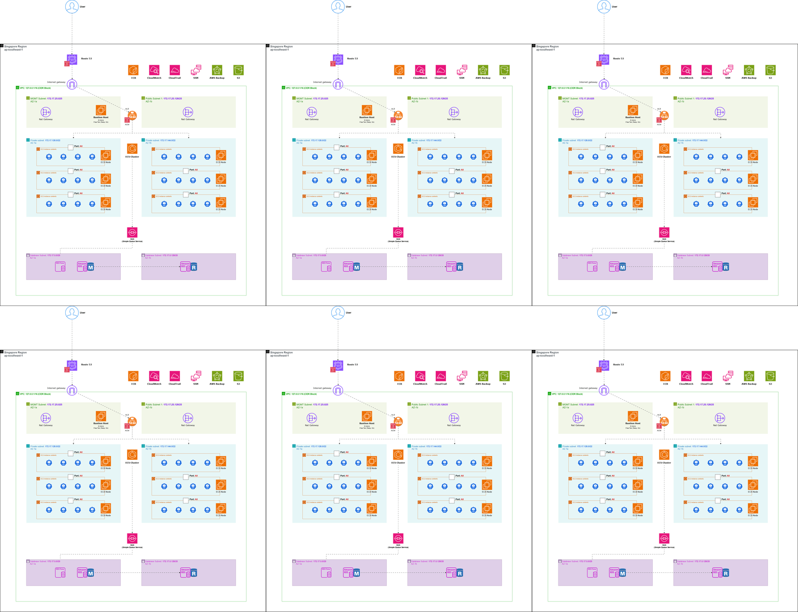
Source topology, redrawn with honest boundaries.
Regional managed services sit outside the VPC; subnet-bound capacity sits inside it. Ambiguous source relationships remain visibly unverified.
Drag service cards to arrange them. Pan or zoom the canvas, select a node for engineering context, or select an arrow to isolate that flow.
What the infrastructure needed to solve
Private runtime
Protect application workloads from direct public ingress while retaining controlled egress.
Failure domains
Distribute compute and data-layer intent across two Availability Zones.
Reproducible releases
Run versioned container artifacts instead of building source on production hosts.
Independent work
Separate synchronous HTTP handling from background processing.
Persistent data
Isolate relational state from replaceable container and EC2 lifecycles.
Operability
Provide monitoring, audit, administration, backup and recovery capabilities.
Seven boundaries that shape runtime behavior
Centralized public ingress
- Problem → decision
- Public callers need one stable, encrypted entry point. Route 53 resolves the hostname; ACM supplies the certificate; a public ALB receives HTTPS and selects healthy ECS targets.
- Runtime behavior
- DNS completes before application traffic. The browser connects to the ALB—not through Route 53.
- Trade-off
- Listener, certificate, subnet mapping, health check and target configuration become critical shared dependencies.
Private application compute
- Problem → decision
- Containers should not accept arbitrary inbound internet traffic. Place ECS EC2 capacity in private application subnets and make the ALB the intended ingress boundary.
- Runtime behavior
- ALB → application target is the expected inbound path; NAT → internet is outbound-only when route tables are correct.
- Trade-off
- Private placement still requires least-privilege security groups, IAM, patching and egress control.
Multi-AZ compute
- Problem → decision
- One Availability Zone must not be the only compute failure domain. The diagram places ECS capacity in AZ-1a and AZ-1b behind a common ALB.
- Runtime behavior
- Healthy targets in the surviving AZ can receive traffic if desired count, placement and spare EC2 capacity allow it.
- Trade-off
- Multi-AZ topology increases resilience and cost, but does not promise zero downtime.
ECS on EC2
- Problem → decision
- Container orchestration is needed with control over the underlying hosts. Use an ECS cluster with EC2-backed capacity; the source depicts three container instances per AZ and repeated workloads.
- Runtime behavior
- ECS places tasks onto available container instances; task demand and host capacity must be reconciled separately.
- Trade-off
- More host control and potentially efficient steady load, in exchange for AMI lifecycle, patching and capacity scaling. Fargate would remove host operations but change cost/control trade-offs.
Immutable container artifacts
- Problem → decision
- Production releases should be traceable and repeatable. Build a Docker image before runtime, store it in a registry, and deploy the selected image to ECS.
- Runtime behavior
- CI/CD → image → registry → ECS task definition is the expected deployment boundary.
- Trade-off
- Tag mutability, retention, vulnerability scanning and rollback conventions must be governed.
Asynchronous workloads
- Problem → decision
- Background work should not extend or destabilize synchronous HTTP requests. Use SQS as a temporal decoupling boundary between an unknown producer and consumer.
- Runtime behavior
- Messages buffer bursts; consumers can retry and scale independently when configured around queue depth.
- Trade-off
- At-least-once delivery concerns, idempotency, visibility timeout, DLQ and poison-message handling must be designed.
Database isolation
- Problem → decision
- Persistent state and database connections need a boundary independent of compute churn. Place RDS resources in database subnets and depict RDS Proxy in front of the primary database.
- Runtime behavior
- ECS → RDS Proxy → RDS is a reasonable interpretation, but the source arrow instead routes SQS toward the data layer ambiguously.
- Trade-off
- RDS Proxy improves connection management but adds cost and behavior to understand. The second RDS instance cannot be called a standby or read replica yet.
DNS is not the request path.
The client first resolves a name, then opens an HTTPS connection to the ALB. Dashed-question paths from the application remain unverified.
Drag service cards to arrange them. Pan or zoom the canvas, select a node for engineering context, or select an arrow to isolate that flow.
Least privilege should follow the traffic chain.
Only 443 is a stated design intent. Application and database ports stay semantic because no security-group configuration was provided.
Drag service cards to arrange them. Pan or zoom the canvas, select a node for engineering context, or select an arrow to isolate that flow.
How the architecture can scale
HTTP load
ALB distributes traffic across healthy ECS targets. More traffic can justify more tasks, but no target-tracking policy is evidenced.
Compute capacity
EC2 capacity must grow before new ECS tasks can be placed. Capacity providers and Auto Scaling groups require verification.
Async work
Queue depth can drive consumer capacity. The source does not identify consumers, alarms or scaling rules.
Database
Connections, reads, writes, storage and failover scale independently. The RDS M/R relationship must be established first.
Architecture capability is not implemented policy. The diagram proves multiple boxes, not the control loops that scale them.
What happens when something fails?
01Container failure
Expected behaviorECS may replace a stopped task and the ALB can stop routing to an unhealthy target.
Dependency / limitationRequires an ECS service, desired count, health checks and available host capacity.
Recovery evidenceNeeds configuration or runtime verification.
02EC2 container instance failure
Expected behaviorTasks may be rescheduled to remaining registered capacity.
Dependency / limitationRecovery depends on capacity provider/Auto Scaling configuration and spare resources.
Recovery evidenceNeeds configuration or runtime verification.
03Availability Zone failure
Expected behaviorThe ALB can route to healthy targets in the surviving AZ.
Dependency / limitationOnly if ALB subnet mappings, cross-zone behavior, task placement and database behavior are correct.
Recovery evidenceNeeds configuration or runtime verification.
04Consumer failure
Expected behaviorSQS can retain an unacknowledged message until visibility timeout expires.
Dependency / limitationRetry count, DLQ, idempotency and consumer monitoring are not evidenced.
Recovery evidenceNeeds configuration or runtime verification.
05Database failure
Expected behaviorA managed failover may be possible depending on the actual RDS deployment mode.
Dependency / limitationThe M/R labels do not prove Multi-AZ, failover targets or application reconnection behavior.
Recovery evidenceNeeds configuration or runtime verification.
06Public target health failure
Expected behaviorThe ALB can remove an unhealthy target from rotation.
Dependency / limitationHealth-check path, thresholds, grace periods and sufficient healthy targets require verification.
Recovery evidenceNeeds configuration or runtime verification.
How CI/CD would reach this architecture
No pipeline evidence was supplied. The source diagram shows ECR, but the actual registry, build system, tag/digest strategy, task-definition update and rollback mechanism all remain needs verification.
Availability, backup and recovery are different promises
CloudWatch
“What is happening?”Metrics, logs and alarms are capabilities; none are proven configured by the image.
CloudTrail
“Who changed what?”Audits AWS API activity; trail destination, retention and alerting need verification.
Systems Manager
Managed administrationCould replace inbound SSH when agents, IAM and network access are configured.
AWS Backup
Recoverable copiesPlans, vaults, retention, protected resources and restore tests are not shown.
Resilience and control are not free
Two NAT Gateways
Availability ↑ AZ-local egress avoids one shared NAT failure domain.
Cost ↑ Hourly and data-processing costs apply to each gateway.
ECS on EC2
Control ↑ Host shape, AMI and reserved capacity stay explicit.
Operations ↑ Patching, draining and scaling the hosts remain yours.
Bastion host
Explicit path Familiar jump-host administration.
Attack surface Another host and credential path to secure.
RDS Proxy
Connection control Pools client connections during task churn.
Managed cost Adds a hop, price and engine-specific behavior.